
impedance control play a role in fpc circuit board design
FPC circuit board is a hardware component used in electronic devices that feature conductive pathways. They are a versatile solution that can be molded into many shapes and sizes, making them a popular choice for portable electronics like cell phones and tablets. They are also used in automotive electronics, wearables and more. In order to ensure that the traces in an fpc circuit board are able to transmit signals properly, the impedance must be controlled. Inconsistent impedance can cause problems such as signal degradation and short circuits. In order to prevent these issues, it is important that designers pay close attention to impedance control during the PCB design process.
The impedance of a PCB is determined by various factors, including trace width, copper thickness and dielectric thickness. In order to ensure that the impedance is consistent, it must be managed across multiple layers of a multilayer PCB. As such, it is important that designers carefully document these specifications in their documentation materials so that they can clearly communicate them to fabricators. In addition, to avoid confusion and delays, it may be helpful for designers to add a chart to their documentation that lays out the impedance requirements in terms of trace width, copper weight and layer thickness.
Impedance control can be a complicated issue to address. For example, if a design calls for a certain trace width, but the fabrication process cannot produce it at that size, then the project will be delayed while the fabricator works on changing the design. Inconsistent impedance can also be caused by incongruent trace width requirements for different layers of the same PCB. This can lead to the fabricator having to stop production and ask the designer which figure should be used.
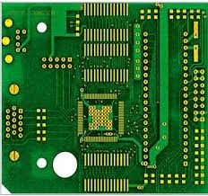
How does impedance control play a role in fpc circuit board design?
When the impedance control is a concern, it is important to use a good quality multilayer fpc circuit board with a metalized hole pattern that allows for good metallization. This will help reduce impedance and provide a reliable product for your application. In addition, the conductive paths can be made of one or more layers of one-sided or two-sided flexible circuit boards. Moreover, the flexible circuit boards are much cheaper than rigid printed circuit boards due to the fact that they do not require complex welding processes.
The advantages of using a multilayer fpc circuit board include higher reliability, better thermal conductivity and improved decoupling between circuits. It is important to note, however, that the dimensional stability of a flexible circuit board is hygroscopic and will change with changes in temperature. This makes it necessary to store the circuit board in a temperature-controlled environment.
Otherwise, it will expand or contract and could result in a shortened life for the circuit. In some cases, the expansion and contraction will be so severe that the circuit board will no longer be usable. If this occurs, it will be necessary to replace the board. This can be an expensive proposition. In addition, if the flex is not properly stored and handled during transport or storage, it could damage the connectors or other components on the board.
